Metal Speed


Order No.

![]() Type
Type
![]() Control Direction
Control Direction
No code : Meter-out control
A : Meter-in control
Flow Direction Symbols on Body
| Meter-out control |  |
 |
| Meter-in control |  |
 |
| Metric system ( MM ) | ||
|---|---|---|
| Code | 4 | 6 |
| Size ( Dia ) | Ø 4 | Ø 6 |
| Metric Thread | BSPT Thread | ||
|---|---|---|---|
| Code | M 3 | M 5 | 01 |
| Size | M 3 x 0.5 | M 5 x 0.8 | PT 1 / 8 |
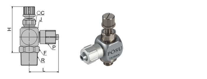
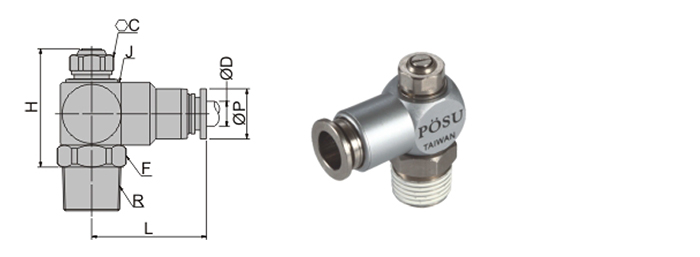
Construction

Package : 1 pc. in a bag
* Minimizes installation time and cost.
* Body swivels 360 ° , swivel type allows free setting of piping .
* The metal part of body is made up of brass and stainless steel.It's chromaim and nickel-plating surface and beautiful exterior.
* The claw is made up of stainless steel to keep using for a long time without elastic exhaustion.
Specifications
| Fluid admitted | Air / Air |
| Service pressure range | 0 ~ 9 kgf / cm 2 ( 0 ~ 900 kPa ) |
| Check vale operating pressure | 0 .5 kgf / cm 2 ( 50 kPa ) |
| Service temperature range | 0 ~ 60 ° C |
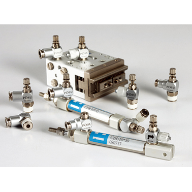
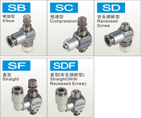
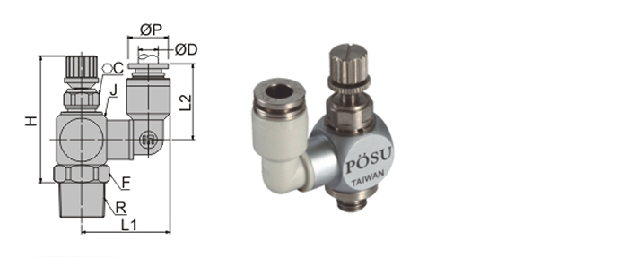
Metal Speed Controller
SB
Elbow

 |
 |
 |
Unit : m / m |
| Model | Tube dia. ØD | ØP | L | R | J | C | H | F | Mass (g) | Orifice | |
|---|---|---|---|---|---|---|---|---|---|---|---|
| MAX | MIN | ||||||||||
| SB □ 4 - M 3 | 4 | 8 | 18.3 | M 3 X 0.5 | 10 | 7 | 28.6 | 26.3 | – | 13.4 | 1.2 |
| SB □ 4 - M 5 | M 5 X 0.8 | – | 13.6 | 2 | |||||||
| SB □ 4 - 01 | PT 1 / 8 | 10 | 18 | 2.2 | |||||||
| SB □ 6 - M 3 | 6 | 10 | 18.8 | M 3 X 0.5 | 10 | 7 | 28.6 | 26.3 | – | 13.4 | 1.2 |
| SB □ 6 - M 5 | M 5 X 0.8 | – | 13.6 | 3.8 | |||||||
| SB □ 6 - 01 | PT 1 / 8 | 10 | 18 | 3.8 | |||||||
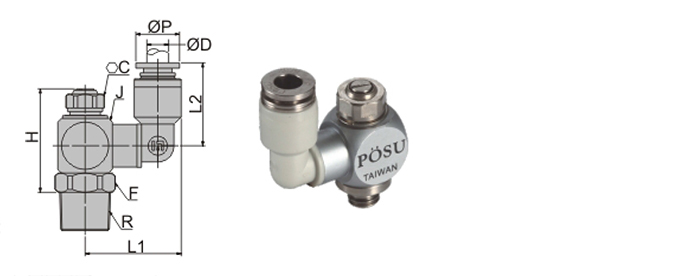
SC
Compression
|
|
|
Unit : m / m |
| Model | Tube dia. ØD | ØP | L | R | J | C | H | F | Mass (g) | Orifice | |
|---|---|---|---|---|---|---|---|---|---|---|---|
| MAX | MIN | ||||||||||
| SC □ 4 - M 3 | 4 | 8 | 16.8 | M 3 X 0.5 | 10 | 7 | 28.6 | 26.3 | 7.5 | 11.8 | 1.2 |
| SC □ 4 - M 5 | M 5 X 0.8 | 13.6 | 2 | ||||||||
| SC □ 4 - 01 | PT 1 / 8 | 18 | 2.2 | ||||||||
| SC □ 6 - M 3 | 6 | 10 | 17.3 | M 3 X 0.5 | 10 | 7 | 28.6 | 26.3 | 10 | 13 | 1.2 |
| SC □ 6 - M 5 | M 5 X 0.8 | 13.6 | 3.8 | ||||||||
| SC □ 6 - 01 | PT 1 / 8 | 18 | 3.8 | ||||||||
SD
Recessed Screw
|
|
|
Unit : m / m |
| Model | Tube dia. ØD | ØP | L | R | J | C | H | F | Mass (g) | Orifice |
|---|---|---|---|---|---|---|---|---|---|---|
| SD □ 4 - M 5 | 4 | 8 | 18.3 | M 5 X 0.8 | 10 | 7 | 18 | – | 11.8 | 2 |
| SD □ 4 - 01 | PT 1 / 8 | 18.9 | 10 | 16.6 | 2.2 | |||||
| SD □ 6 - M 5 | 6 | 10 | 18.8 | M 5 X 0.8 | 10 | 7 | 18 | – | 11.6 | 3.8 |
| SD □ 6 - 01 | PT 1 / 8 | 18.9 | 10 | 16.4 | 3.8 |
SF
Straight
|
|
|
Unit : m / m |
| Model | Tube dia. ØD | ØP | L | L 2 | R | J | C | H | F | Mass (g) | Orifice | |
|---|---|---|---|---|---|---|---|---|---|---|---|---|
| MAX | MIN | |||||||||||
| SF □ 4 - M 3 | 4 | 8 | 17.6 | 15.1 | M 3 X 0.5 | 10 | 7 | 28.6 | 26.3 | – | 12.4 | 1.2 |
| SF □ 4 - M 5 | M 5 X 0.8 | – | 13.6 | 2 | ||||||||
| SF □ 4 - 01 | PT 1 / 8 | 10 | 18 | 2.2 | ||||||||
| SF □ 6 - M 3 | 6 | 10 | 20.2 | 16.1 | M 3 X 0.5 | 10 | 7 | 28.6 | 26.3 | – | 13.4 | 1.2 |
| SF □ 6 - M 5 | M 5 X 0.8 | – | 13.6 | 3.8 | ||||||||
| SF □ 6 - 01 | PT 1 / 8 | 10 | 18 | 3.8 | ||||||||
SDF
Straight ( With Recessed Screw )
|
|
|
Unit : m / m |
| Model | Tube dia. ØD | ØP | L | L 2 | R | J | C | H | F | Mass (g) | Orifice |
|---|---|---|---|---|---|---|---|---|---|---|---|
| SDF □ 4 - M 5 | 4 | 8 | 17.6 | 15.1 | M 5 X 0.8 | 10 | 7 | 18 | – | 10.2 | 2 |
| SDF □ 4 - 01 | PT 1 / 8 | 19 | 10 | 17.2 | 2.2 | ||||||
| SDF □ 6 - M 5 | 6 | 10 | 20.2 | 16.1 | M 5 X 0.8 | 10 | 7 | 18 | – | 11.6 | 3.8 |
| SDF □ 6 - 01 | PT 1 / 8 | 19 | 10 | 17.8 | 3.8 |