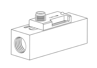
FC210 Flow Switch
Feature
- Sensors and controllers: flow/pressure/temperature/level/position
- Online installation, mechanical flow switch, used for liquid or gas media.
- Rugged plastic, aluminum or stainless steel housing available.
- Minimal pressure loss, good repeatability, anti-fouling ability, complete isolation of mechanical part and electronic part, suitable for small flow and economical type.
- With switch setting scale, users do not need to set it on site.
- LED display indicates switch status, and dual switch outputs are available.
- Application: gas-liquid dual-purpose, industrial automation/machinery equipment/air compression industry/refrigeration and air conditioning.
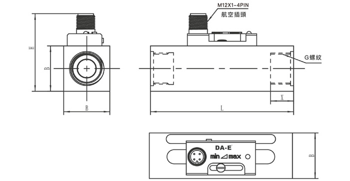
Dimensional Drawing

Technica Parameters
| Setting range | Please see the parameter table for details |
|---|---|
| Accuracy | Total range ±20% |
| Hysteresis | Depending on switching point, minimum 0.3 L/min |
| Switch setting scale (installation position) | The medium is water, the temperature is 20°C, and the calibration is carried out in a horizontal installation state (changes in medium and temperature will have a slight impact on the switch value) |
| LED display | DC power supply LED displays switch status, AC has no LED display |
| Wiring method | M12 connector |
| Output | Reed switch, capacity 24VDC / 250VAC, 100mA |
| Pressure resistance | 10 bar (plastic) / 50 bar (aluminum) / 100 bar (stainless steel) |
| Average pressure loss | 0.3 bar (at 25 L/min) |
| Medium temperature | Max 100°C |
| Protection level | IP65 |
| FC210 / S material | Housing - POM plastic / Piston - POM plastic / Seal - NBR |
| FC210 / L material | Housing - Anodized Aluminum / Piston - POM Plastic / Sealing - NBR |
| FC210/X Material | Housing - Stainless Steel / Piston - POM Plastic / Sealing - NBR |
Type
| Model | Pressure (bar) | Maximum traffic L/min (water) |
Adjustable range L/min (water) |
G (mm) |
L (mm) |
H (mm) |
B (mm) |
X (mm) |
Weight (KG) |
|---|---|---|---|---|---|---|---|---|---|
| FC210- 020...L(S)008 |
50 | 40 | 0.6(0.3)...8(7) | G 3/4 | 109 | 54 | 34 | 15 | 0.23 (0.65) |
| FC210- 025...L(S)008 |
50 | 40 | 0.6(0.3)...8(7) | G 1 | 109 | 56 | 40 | 15 | 0.32 (0.82) |
| FC210- 008...L(S)015 |
50 | 40 | 1(0.5)...15(13) | G 1/4 | 93 | 52 | 30 | 12 | 0.22 (0.53) |
| FC210- 010...L(S)015 |
50 | 40 | 1(0.5)...15(13) | G 3/8 | 93 | 52 | 30 | 12 | 0.20 (0.51) |
| FC210- 015...L(S)015 |
50 | 40 | 1(0.5)...15(13) | G 1/2 | 93 | 52 | 30 | 12 | 0.18 (0.48) |
| FC210- 020...L(S)015 |
50 | 40 | 1(0.5)...15(13) | G 3/4 | 109 | 54 | 34 | 15 | 0.23 (0.65) |
| FC210- 025...L(S)015 |
50 | 40 | 1(0.5)...15(13) | G 1 | 109 | 56 | 40 | 15 | 0.32 (0.82) |
| FC210- 015...L(S)025 |
50 | 40 | 2(0.8)...25(25) | G 1/2 | 93 | 52 | 30 | 12 | 0.18 (0.48) |
| FC210- 020...L(S)025 |
50 | 40 | 2(0.8)...25(25) | G 3/4 | 109 | 54 | 35 | 15 | 0.23 (0.65) |
| FC210- 025...L(S)025 |
50 | 40 | 2(0.8)...25(25) | G 1 | 109 | 56 | 40 | 15 | 0.32 (0.82) |
| FC210- 020...L(S)070 |
50 | 40 | 27(21)...70(66) | G 3/4 | 115 | 62 | 40 | 15 | 0.23 (0.65) |
| FC210- 025...L(S)070 |
50 | 40 | 27(21)...70(66) | G 1 | 115 | 62 | 40 | 15 | 0.32 (0.82) |
Installation Note
Installation Notes!
1 To avoid electric shock and damage to the equipment, the power supply should be cut off when wiring or debugging.
2. When wiring, it is absolutely prohibited to adjust screws other than the micro switch terminals and grounding screws.
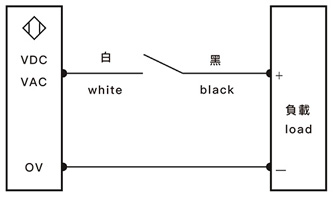
Connecting Diagram

The switch is a normally open contact
It is forbidden to connect the white and black wires directly to the positive and negative poles of the power supply, otherwise it will cause the switch to short-circuit.
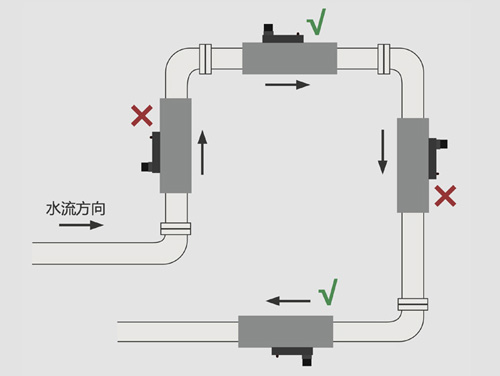
Installation Example


